Mouldings at the right height first, channels after
Do not place the channels to the dimensions of the drawing: dry-fit the mouldings at height first, mark the channels on them and only then fix everything, so mouldings and channels are right relative to each other. The manual almost does it this way (12.2: mark one channel loosely, 12.5: leave the moulding open at the channel, 21.3: pin and glue), except that it measures from the drawing, which on our hull no longer matches.
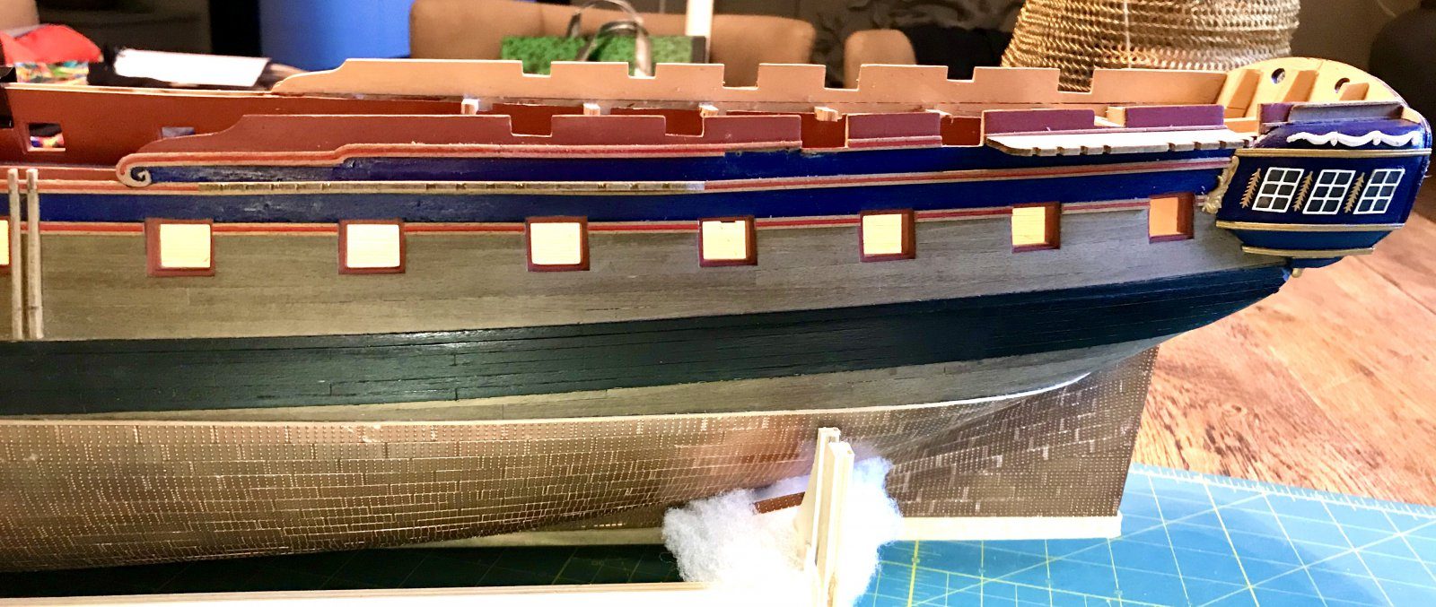
What you need
- pencil
- hobby knife
- small clamps
- small drill for the pin holes
- callipers or ruler
- fore channels 56, main channels 57, mizzen channels 55 (the manual says 58, but that is the gallery taffrail) and the small backstay stools 142; 2 mm walnut
- 1 mm brass wire (316) as a locking pin through the channel into the hull (drawing 17)
- mouldings from the kit (laser-cut parts and loose strips)
- PVA glue
- pins for the channels
Dimensions
- locking pin 1 mm brass wire (316) through the channel into the hull
- 0.7 mm holes for headless pins when placing temporarily (pietsan)
- Time
- several evenings
- Difficulty
- moderate
- When in the build
- Phase 6,
- From the log post
- Mouldings first channels after · forum
Before you start
The hull is planked, painted and coppered, the wale is on. Know where your lines come from: we followed the drawing, which matches the photo on the cover of the Anatomy book and differs considerably from the lines on Piet's model. Expect the drawing not to match your model to the millimetre; on ours the gunports sit slightly too low.
Dry-fit the channels on the hull where drawing and common sense put them, purely to see how the mouldings have to run round them. Do not glue them and do not drill any holes in the hull yet; the position will still move. Pietsan did drill holes, but in the channel itself: two or three of 0.7 mm at an angle in the inner edge, with headless pins in them; a few taps with a small hammer mark the holes in the hull, pre-drill, and until the final gluing the channel goes back in exactly the same place every time (modelbouwforum, 3 March 2015, forum post). Check that the chainplates under the channels will not run across a gunport, especially at the forward channel.
0.7 mm holes in the inner edge of the channel (pietsan)
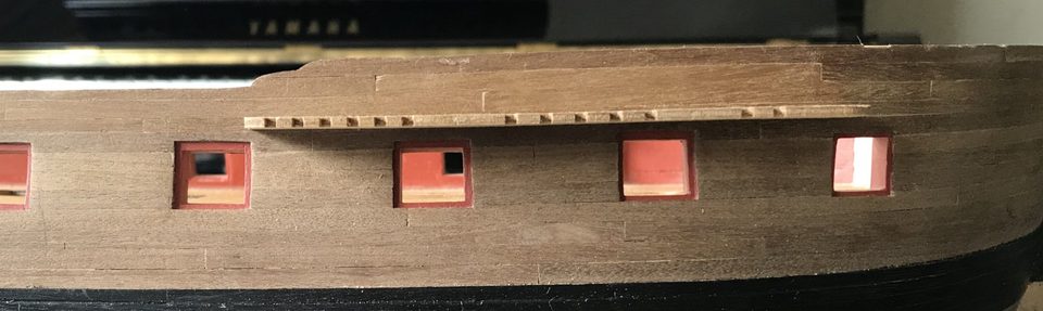
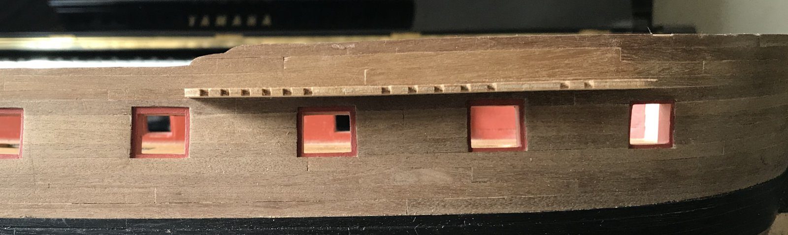
A channel dry-fitted above the gunports: here you can see whether the chainplates will clear the ports later. Tip from janzwart: The chainplates, the supports under the channels, must not run across the gunports. At the mizzen channel they do sit above the ports, as pietsan added, but forward it works out differently.
Watch out: We had to move the channels several times relative to what we had measured from the drawing. The drawing differs too much from the model as it eventually turns out to place the channels to the millimetre.
First lay the mouldings loose on the hull at the height you are following, held with a few clamps or bits of tape. Look from a distance to see whether the mouldings run nicely parallel to the wale and the sheer, and whether they fall neatly between and around the ports. Adjust the height until it matches what you see, not what the drawing says.
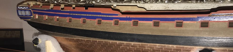
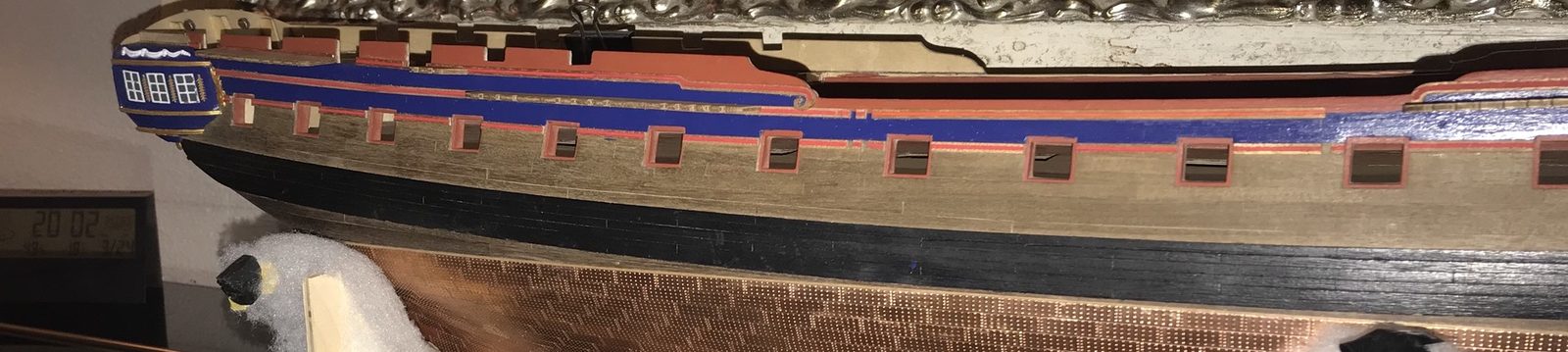
The mouldings along the whole length of the hull, laid to the lines of the drawing; the channels still sit loose in them. Slide the loose channels against the dry-fitted mouldings and mark in pencil on the moulding where each channel goes. That fixes the position of the channel relative to the moulding, rather than relative to a drawing that the model no longer entirely is.
Tip from pietsan: Put the mast temporarily in the model and stretch a thread from the top to each deadeye slot. Put a pencil mark where the thread crosses the wale: that is the position of the chainplate, and you see straight away whether one runs across a port. (modelbouwforum, 27 April 2015)
Take the moulding off the hull and at the marked spot cut away the top or bottom edge of the moulding, so the channel will drop in exactly. Cut away slightly too little rather than too much and trim afterwards; an oversized notch shows later.
Tip from pietsan: Let the moulding stand 1 mm proud above the channel and carry that line across the channel with a 1 x 1 mm strip, so moulding and channel form one whole. At the mizzen channel the lower moulding runs exactly across the channel. (modelbouwforum, 5 April 2015)
Glue the notched moulding at the agreed height and clamp it every few centimetres, especially on curves. Before the glue dries, check once more from the side that the moulding has not shifted.
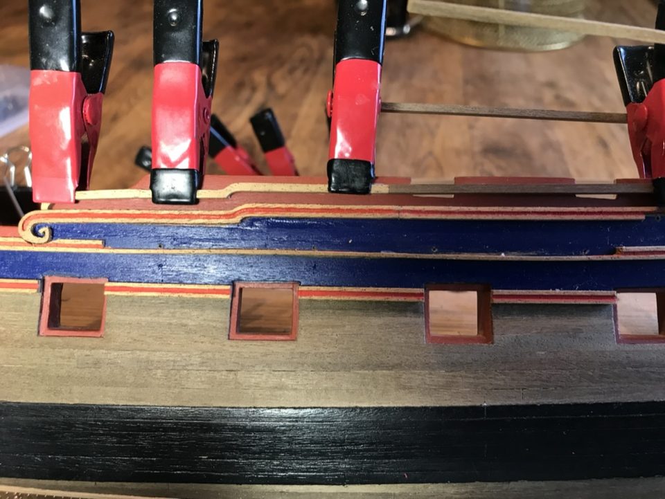
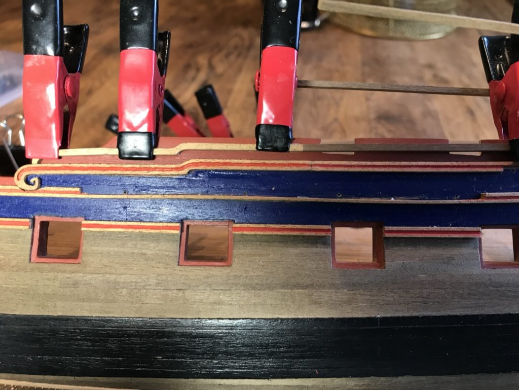
A moulding on the port side glued with a row of small clamps, the gunports below it clear. Set the channel in the notch of the glued moulding. Still dry-fitted, but now drill the holes for the pins, because the position is fixed. Only fix the channel for good once the eyebolts (313) for the backstay tackles and the iron knees (258) are on it and everything is painted black; that is far easier on a loose channel. Then pin it with 1 mm brass wire (316, drawing 17) through the channel into the hull and glue afterwards.
locking pin 1 mm brass wire (316)
Watch out: Walter de bouwer had already glued his channels when pietsan asked whether he had, because rings, paint and knees still had to go on (modelbouwforum, 2 February 2016, forum post). Peterhudson broke a glued-only channel off the hull while pushing in a deadeye (Model Ship World, 6 June 2020, forum post). So pin, and glue.
Result
With this order everything sits right relative to everything else and you never have to move a channel that is already pinned in place. The difference from the manual is one point only: we measure from the dry-fitted mouldings instead of from the drawing.
In the same series: Stern and ornaments
- Five trials for the transom windows
- Fitting the quarter gallery windows with a small frame as a jig
- Repairing a white metal figure with solder
- Painting gold-coloured carvings
- Applying the red line in the profile of the mouldings
- Mouldings at the right height first, channels after
- Bending a one-piece moulding round the bow
- Making the stern port lids with a template